Overview
I got the idea of the Kalk reactor from a lot of different sources. The main idea of cutting it out of PVC sheet came from a forum member on reefcentral.com . He did something very similar using a magnetic stirrer in the base.
After looking at designs on the web, I decided I wanted to use a motor and paddle to keep the slurry stirred in the bottom of the container. I also wanted to make sure my pH probe would fit in the top where the water comes out. Right now it rests on the bottom of my top-off tank and I think that affects it’s reading.
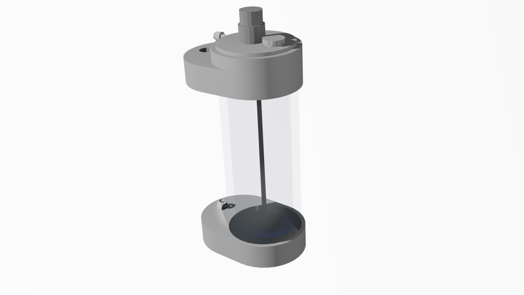
The design consists of a base, top and a standard piece of 4″ PVC pipe 12″ long. The size is more of a restriction on the inside of my stand than anything else. I would have preferred it to be taller. A lot of designs out there use clear PVC. It’s expensive. I’m hoping with the pH probe I can use science to figure out when I need to add more calc instead of having to ‘see’ how much is in it.
I will be using a small electric geared motor on the top to turn a paddle on the bottom. The section of the lid with the motor will be threaded so I can remove it for cleaning the inside when needed. I’m hoping I can make a smaller opening in the lid that I can remove when I need to add more Kalk.
Hardware
- DC 30RPM Electric Motor
- Electric Motor Controller (Will allow me to fine tune the paddle speed)
- 1/4″ Hose Fitting for 1/4″ NPT hole
- 90 degree 1/4″ Hose Fitting for 1/4″ NPT hole
- 2x 1/4″ Valve (Optional for removing reactor for cleaning)
- 12V Power Supply (I already have one, but this should work)
- pH Probe (The threads and design are for this one. If you have a different probe, you may need to get a 3/4″ to 1/2″ adapter to put it in Like This)
Materials
- 4″ PVC 12″ Long (taller if your stand will allow)
- 3/4″ PVC 12″x24″ (My CAM layout shows that all the pieces should fit)
- PVC Glue
- PVC Primer
- ABS filament
Tools Needed
- CNC Machine (parts could probably be hand cut, but the large thread on the lid would be difficult)
- 1/8″ End Mill
- 3/8″12 Thread Mill (A larger thread would make it easier to put the lid on/off, but I’m limited to the 1/4″ collet my spindle has)
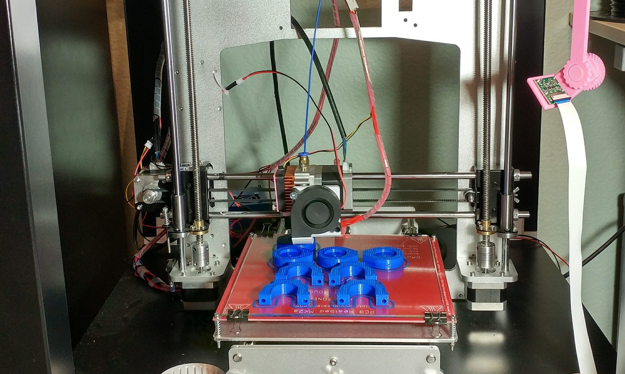
- 3D Printer (stirrer is 3d printed)
- 1/4″-18 NPT-Taper Tap
- 3/4″-14 NPT Tap
- Saw (anything you can cut the PVC pipe with)
- Drill Bit (The PVC pipe needs 1 hole drilled near the top for the water to flow out of
Build
After designing a few of the pieces in Inventor, I set to work on cutting some of them out and test fitting the PVC pipe. My .02″ tolerance is a bit on the tight side, but I think it will work. I did have to use a small mallet to seat some of the pieces.
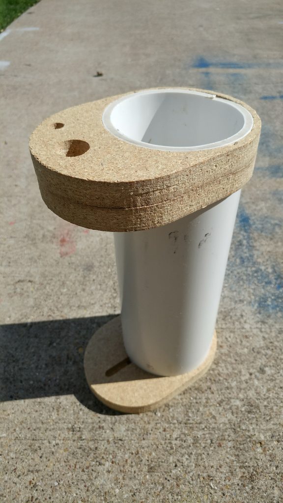
When I finally got all the parts cut out, it was time to test fit. I found out a few things…
- The motor holes didn’t line up with the motor. They all need to be moved over
- The Hose barbs I have on hand are a different size then what I designed for
- All of the pieces that slide onto the PVC Pipe are too tight
- None of the parts that slide into another part have enough tolerance
- My MDF board was slightly warped making for weird parts fit. Hopefully the PVC flat sheet doesn’t have this problem
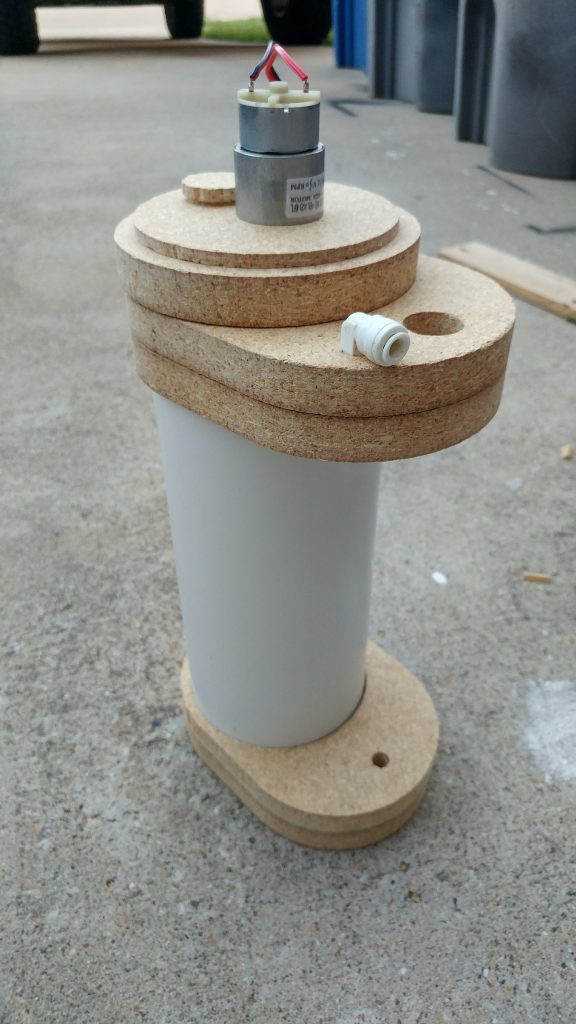
After spending quite some time tinkering in CAD I found out part of my issues were that the different CAM process types had different default configurations. The 2d Pocket process leaves a default .02″ so that you can come back with a 2D contour to clean up the final edge.
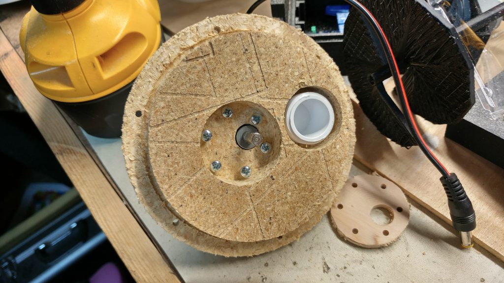
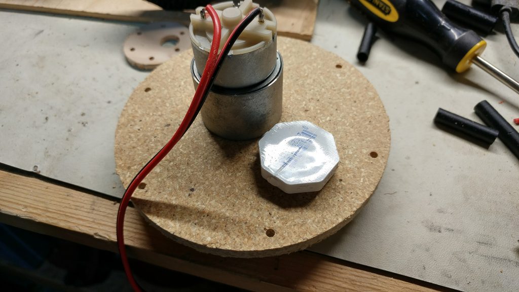
I massaged all the design files and got my first ‘final draft’ of one of the parts cut. I also adjusted the design to remove the large threaded parts. I’ll use simple M3 bolts to hold the lid onto the rest. This reduces complexity and keeps me from having to buy a $45 thread mill. In the first picture, you can also see the small plywood piece I cut to verify the motor mount was correct before wasting another chunk of MDF.
